-

企业介绍
致力于世界级的光通信研发与创新,创无限光电子信息世界,改善人们的生活品质

企业历史
腾天科技有限公司成立于2000年
2001年腾天在深圳建立工厂
2003年腾天进入国际市场并在全球80多个...


简单描述:
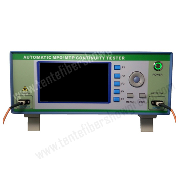
MPO/MTP 极性测试仪 TPR8805
详细介绍:

1.Overview
1.1 Product Introduction
Automatic MPO/MTP Continuity Tester is a kind of intellectualized product to analyze fiber optic patch cords sequence and judge break fiber optic patch cords In the process of the production of MPO/MTP fiber optic patch cords. The tester adopts the visible red light as the light source, it not only can detect the MPO/MTP fiber optic patch cords’ sequence, can also detect fiber optic patch cords sequence to MPO-FAN. This tester is easy to use, which has a 7 inch color LCD. Obviously, the test results are transparent. It provides a great convenience for producing fiber optic patch cords and testing half-finished or finished fiber optic cords.
1.2 Main Functions
(1) Test 12 or 24 channels MPO/MTP fiber optic patch cords by a machine;
(2) Detect fiber optic patch cords sequence to 12 or 24 channels MPO-FAN;
(3) Fast detection speed and quick response;
(4) Display by 7 inch color LCD;
(5) Detect 9/125, 50/125, 62.5/125 fiber optic patch cord core;
(6) Support alam sound when The product is unqualified;
(7) Support user-defined MPO/MTP fiber optic patch cords’seque-
nce, all important data does not disappear when the tester shutdown.
1.3 Specifications
Num of Channel | 12 or 24 channels |
The Types of Optical Fiber Can Be Detected | SMF: 9/125 MMF: 50/125 and 62.5/125 |
Test Time | <1s |
Place of Origin | |
Interface Type of Light Output | MPO/PC 24-core male connector |
Interface Type of Light Input | MPO/PC 24-core male connector |
Communication Interface | USB |
LCD | 7 inch color LCD |
Power Source | AC100~240V 50HZ |
Working Tem.(℃) | 0~+40 |
Storage Tem. (℃) | -10~+60 |
Dimension | 355mm*300mm*137mm |
1.4 Configuration Instructions
(1) Standard compositions
NO. | Names | Quantity |
1 | Automatic MPO/MTP Continuity Tester | 1 |
2 | Power cord | 1 |
3 | User manual | 1 |
(2) Reference fiber optic tieline(MPO/PC)
Specifications of fiber optic cords whitch are tested | Fiber optic tieline | NO. | |
24-core | Female connector to female connector | No need | 0 |
Female connector to male connector | Female connector to female connector | 1 | |
Male connector to male connector | Female connector to female connector | 2 | |
12-core | Female connector to female connector | 24-core female connector to 12-core male connector | 2 |
Female connector to male connector | 24-core female connector to 12-core male connector | 1 | |
24-core female connector to 12-core female connector | 1 | ||
Male connector to male connector | 24-core female connector to 12-core female connector | 2 | |
(3) Options
1 | 24-core MPO/PC Multimode female connector of type A to 24-core MPO/PC Multimode female connector of type A fiber optic patch cord |
2 | 24-core MPO/PC Multimode female connector of type A to 12-core MPO/PC Multimode male connector of type A fiber optic patch cord |
3 | 24-core MPO/PC Multimode female connector of type A to 12-core MPO/PC Multimode female connector of type A fiber optic patch cord |
4 | MPO standard adapter |
2.Operation Panel Introduction
2.1 Front Operation Panel

(1) OUTPUT: MPO standard adapter, visible red light output;
(2) INPUT: MPO standard adapter, visible red light output;
(3) F1,F2,F3,F4,F5: quick function keys;
(4) POWER: power switch;
(5) MENU: menu key;
(6) ESC: return key, the parameters is invalid when the return key was pressed. In addition, there are up key, down key , right key, left key and enter key above menu key and return key.
2.2 Back Operation Panel

(1) USB: USB communication interface;
(2) LOG: foot pedal;
Moreover, there have a fan on the back operation panel in order to timely heat dissipation.
- 上一篇:TPR-0616 MPO多芯光纤显微镜
- 下一篇:全自动点胶机 TPR-8808